


Views: 0 Author: Site Editor Publish Time: 2026-10-12 Origin: Site


The rapid transition to electrified powertrains, high-voltage architectures, and advanced ADAS has exponentially increased the electromagnetic complexity of modern vehicles. Failing Electromagnetic Compatibility (EMC) compliance late in the development cycle leads to severe production delays, costly redesigns, and potential safety liabilities. Relying on inadequate testing infrastructure results in false passes, excessive testing downtime, and bloated certification budgets. Selecting the right automotive EMC test system requires moving beyond basic RF measurement. It demands a strategic evaluation of current compliance standards, facility constraints, process efficiency, and future-proof scalability for next-generation EV platforms to ultimately reduce testing cycles and accelerate time-to-market.
Align system capabilities strictly with global automotive standards (CISPR 12/25, ISO 11451/11452) and proprietary OEM specifications, distinguishing them from generic commercial or military requirements.
Determine the necessary scope of testing early, differentiating between component-level pre-compliance setups and full-scale, whole-vehicle anechoic chambers.
Account for the unique high-voltage and high-current challenges of EV powertrains by evaluating specialized load simulation equipment, such as an EMC E-motor Test Bench or EMC E-Axles Test Bench.
Evaluate the overall facility investment by factoring in chamber size limitations, calibration requirements, safety protocols, and the efficiency of automated test execution software.
Baseline equipment requirements must map directly to global regulatory standards. Key frameworks include CISPR 12 for off-board emissions, CISPR 25 for on-board component emissions, ISO 11451 for whole-vehicle immunity, and ISO 11452 for component-level immunity. These standards dictate the minimum acceptable limits for electromagnetic interference. Automotive testing requires specific frequency ranges, often spanning from 150 kHz up to 6 GHz, utilizing measurement techniques not found in consumer electronics. You must configure your hardware to handle these exact parameters without deviation.
Proprietary OEM specifications frequently exceed baseline regulatory limits. Automakers like Ford, General Motors, and Volkswagen impose stricter frequency ranges and higher immunity thresholds to ensure vehicle reliability under extreme conditions. For example, some OEM standards require radar pulse immunity testing at field strengths exceeding 600 V/m. Your testing infrastructure must accommodate these elevated requirements. Failure to meet OEM-specific standards results in rejected components and lost supplier contracts. Always verify that your amplifiers and antennas can generate the extreme field strengths demanded by top-tier manufacturers.
Ensure the selected system is purpose-built for automotive applications. Avoid the pitfalls of retrofitting generic commercial or military EMC equipment. Automotive environments involve unique grounding structures, specifically the use of a continuous copper ground plane bonded to the shielded enclosure. Military standards like MIL-STD-461 utilize different test setups, LISN impedances, and limit lines. Using adapted equipment introduces measurement errors, creates impedance mismatches, and compromises compliance validity.
Establish a traceable test plan framework from day one. All collected data must meet the strict documentation and audit standards required by certification bodies. This ensures data integrity for future testing and product iterations. Automated logging, secure data storage, and unalterable timestamping are mandatory. Traceability protects your organization during compliance audits and simplifies root-cause analysis when troubleshooting emission failures during the development phase.
Standard | Application Scope | Key Measurement Focus | Typical Frequency Range |
|---|---|---|---|
CISPR 12 | Whole Vehicle | Off-board radiated emissions (protecting external receivers) | 30 MHz – 1 GHz |
CISPR 25 | Components / Modules | On-board radiated and conducted emissions | 150 kHz – 2.5 GHz (or higher) |
ISO 11451 | Whole Vehicle | Radiated immunity to external electromagnetic fields | 10 kHz – 18 GHz |
ISO 11452 | Components / Modules | Radiated immunity and Bulk Current Injection (BCI) | 100 kHz – 6 GHz |
Assess the required scope of testing before designing the facility. You must decide whether to isolate sub-assemblies or evaluate full vehicle integration. Component-level testing focuses on individual Electronic Control Units (ECUs), traction inverters, and battery management systems. Whole-vehicle EMC testing evaluates the entire vehicle under simulated operating conditions. Each approach requires vastly different infrastructure, physical space, and power resources.
Evaluate spatial and load requirements carefully. The Device Under Test (DUT) must fit comfortably within the testing chamber. It cannot compromise the quiet zone or violate antenna distance standards. Component chambers are relatively compact, typically utilizing 3-meter or 5-meter semi-anechoic designs. Whole-vehicle chambers require massive 10-meter footprints and specialized hybrid RF absorbers to maintain field uniformity across a much larger volume. Miscalculating chamber dimensions invalidates test results and requires expensive facility modifications.
Address the logistical challenges of whole-vehicle testing early in the planning phase. Consider vehicle ingress and egress pathways, ensuring chamber doors are wide enough for commercial chassis if necessary. Assess structural floor limits to support heavy EV battery packs and dynamometers. You must manage exhaust routing and fuel lines for hybrid or internal combustion engine vehicles. Testing ICE vehicles alongside EVs requires specialized ventilation systems utilizing waveguide air vents that do not degrade the chamber's RF shielding effectiveness.
Analyze the operational benefits of establishing in-house pre-compliance testing. In-house capabilities reduce reliance on third-party certification labs. They allow engineers to test iteratively, apply copper tape or ferrite beads on the fly, and identify failures early. This approach shortens development cycles and prevents late-stage redesigns. While the initial setup requires capital, the reduction in external lab fees and accelerated development timelines justify the investment for high-volume manufacturers.
Specify technical requirements for EMI receivers and spectrum analyzers based on required frequency bands. Automotive testing now demands measurements up to 6 GHz for standard compliance, and up to 100 GHz for advanced radar modules. Sweep speeds must be fast enough to capture transient emissions from fast-switching power electronics. Modern FFT-based (Fast Fourier Transform) time-domain receivers reduce scan times from hours to minutes. Ensure your receivers comply fully with CISPR 16-1-1 requirements for peak, quasi-peak, and average detectors.
Evaluate the necessary array of broadband antennas, pre-amplifiers, and field probes. Focus on sensitivity and linearity under high-field conditions. Biconical antennas handle lower frequencies, log-periodic antennas cover the midrange, and dual-ridge horn antennas manage the microwave spectrum. Pre-amplifiers must offer low noise figures to detect faint emissions near the limit lines. Field probes require high damage thresholds to survive the intense RF fields generated during ISO 11452-2 immunity testing.
Define the requirements for Line Impedance Stabilization Networks (LISNs). Automotive applications require specialized 5µH LISNs for DC and high-voltage AC networks, differing from the 50µH LISNs used in commercial electronics. These devices isolate the DUT from power supply noise. They provide a standardized impedance for repeatable conducted emission measurements. EV testing requires high-current LISNs capable of handling hundreds of amps without magnetic core saturation or thermal failure.
Select EMI receivers with real-time spectrum analysis capabilities to catch intermittent transients.
Specify antennas with low Voltage Standing Wave Ratio (VSWR) for efficient power transfer.
Implement high-current LISNs rated for 1000V DC and 500A continuous operation.
Deploy optically coupled field probes to prevent the probe cables from acting as unintended antennas.
Utilize low-loss RF cables with armored jackets to withstand the harsh mechanical environment of a test lab.
Analyze the necessity of low-emission, heavy-duty turntables. Precise, repeatable positioning is mandatory during both pre-compliance and full compliance phases. Turntables must rotate heavy vehicles or components without introducing mechanical or electrical noise into the measurement environment. Automated antenna masts ensure accurate height adjustments and polarization changes (horizontal to vertical). Both systems must operate smoothly under remote control from outside the shielded enclosure via fiber-optic links.
Detail the integration requirements for an EMC Chassis Dyno System. This equipment simulates real-world driving loads, dynamic braking, and regenerative cycles. It operates under active electromagnetic fields. The dynamometer must not introduce parasitic emissions into the chamber. It requires extensive RF shielding, filtered control lines, and specialized grounding to maintain the chamber's ambient noise floor. The dyno rollers must integrate seamlessly into the turntable, allowing the vehicle to be rotated while under load.
Address the unique electromagnetic interference profiles generated by high-voltage switching frequencies. EV inverters and power electronics utilize silicon carbide (SiC) or gallium nitride (GaN) switches. These components operate at extremely high frequencies and fast slew rates (high dV/dt). They generate severe broadband and narrowband common-mode noise. Your measurement hardware must capture these high-frequency transients accurately. Standard receivers often saturate under these conditions, requiring specialized transient limiters and high-dynamic-range front ends.
Define the rigorous safety, shielding, and isolation requirements for testing high-voltage systems. Battery packs and charging infrastructure present significant electrical hazards. The chamber must isolate these high-voltage sources from the measurement equipment and operators. Specialized feed-through filters are required to bring high-voltage DC power from external battery simulators into the chamber without compromising RF integrity. These filters must handle massive currents while providing high insertion loss across the test frequency range.
Implement strict operator safety protocols. High-voltage interlocks must disable power instantly if a chamber door opens during a test. Automated emergency shutdown procedures are non-negotiable. You must install specialized fire suppression systems tailored for lithium-ion battery risks. Standard water sprinklers are insufficient and dangerous when dealing with high-voltage DC. Use gas-based systems or specialized misting systems designed specifically for thermal runaway scenarios.
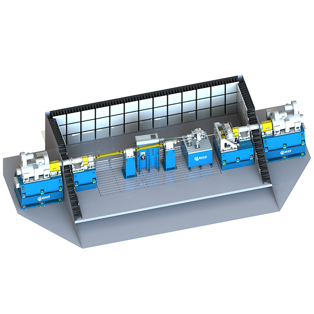
Establish criteria for selecting an EMC E-motor Test Bench. This equipment must handle dynamic load variations and high RPMs. It must maintain strict RF shielding and safe operation throughout the test cycle. The bench simulates the mechanical load of the vehicle while the motor operates under high voltage. The drive shafts connecting the motor inside the chamber to the load machine outside must be non-metallic (often carbon fiber or specialized composites) and pass through a precisely engineered waveguide to prevent antenna effects.
Outline the integration requirements for an EMC E-Axles Test Bench. E-axles combine the motor, transmission, and power electronics into a single integrated assembly. Validating these complex units requires realistic operational stresses. The test bench must support multi-axis loading and high torque outputs. It must interface directly with the chamber's automation software to synchronize mechanical loads with RF sweeps, ensuring emissions are measured precisely during peak torque or regenerative braking events.
Assess the cooling and fluid management systems required for continuous high-power testing. EV powertrains generate massive amounts of heat during operation. You must remove this heat without disrupting the chamber's RF integrity. Use shielded fluid lines and dielectric coolants. The cooling system must prevent thermal shutdowns during lengthy immunity tests. Ensure all pumps, chillers, and heat exchangers are located outside the shielded boundary, with fluids passing through specialized honeycomb waveguide penetrations.
Specify non-conductive, low-inertia drive shafts for motor test benches to prevent RF leakage.
Implement dual-loop cooling systems to manage inverters and stators independently.
Integrate vibration monitoring on the dyno bearings to prevent mechanical failures during high-speed runs.
Use shielded optical fiber for all data acquisition sensors (temperature, vibration, torque) inside the chamber.
Install battery simulators with regenerative capabilities to sink power back to the grid during braking tests.
Assess software platforms for automated test execution and limit-line checking. Manual testing is slow and prone to human error. Automation software executes complex test sequences directly from standard libraries. It controls the signal generators, amplifiers, receivers, and positioning equipment simultaneously. This integration significantly reduces test downtime and enhances overall process efficiency. Engineers can load a specific OEM profile, and the software automatically configures the instruments, sets the antenna height, and begins the sweep.
Look for centralized control systems that synchronize all hardware components. The measurement hardware, turntables, and dynamometers must work together. When the dynamometer simulates a hard acceleration profile, the software should trigger the EMI receiver to capture the resulting emissions at that exact millisecond. This synchronized approach accelerates testing cycles and provides a more accurate representation of real-world vehicle behavior under dynamic loads.
Evaluate report generation capabilities. The software must provide a verifiable, traceable document trail. Certification bodies require detailed reports showing test setups, equipment calibration data, ambient noise sweeps, and measurement results plotted against limit lines. Automated reporting tools format this data instantly for immediate compliance analysis and OEM submission. This eliminates hours of manual data entry and formatting, allowing engineers to focus on mitigation rather than paperwork.
Evaluate the system's modularity to accommodate future frequency bands. Automotive technology evolves rapidly. Advanced ADAS radar systems, V2X communications, and automotive 5G/6G networks operate at much higher frequencies than traditional components. Your chamber and measurement hardware must support upgrades up to 100 GHz. Ensure the RF absorbers and shielding materials are rated for these higher frequencies. Upgrading a chamber later often requires stripping the walls to the bare shielding, which halts testing for months.
Assess hardware upgrade paths carefully. Pre-compliance systems should scale to achieve full compliance status as testing demands grow. You might start with a 100-watt solid-state amplifier and upgrade to a 500-watt Traveling Wave Tube (TWT) amplifier later for higher immunity fields. Ensure the software platform supports third-party hardware additions via standard protocols like SCPI or VISA. A closed ecosystem limits your ability to adapt to new vehicle architectures and testing standards.
Compare the accelerated deployment of turnkey systems against the flexibility of piecemeal integration. Turnkey solutions offer guaranteed interoperability and customized testing workflows. The vendor manages the entire installation, from the steel shielding panels to the final software configuration. Custom integrations allow you to select best-in-class components from multiple vendors. This approach offers flexibility but requires significant internal engineering resources to make disparate systems communicate effectively.
Evaluate vendor support infrastructure before making a decision. EMC test systems require regular maintenance and calibration to maintain ISO 17025 accreditation. Ensure the vendor provides local calibration services and rapid technical troubleshooting. Long-term warranty structures protect the investment. A system that sits idle due to a lack of spare parts or software support severely impacts vehicle development timelines and delays product launches.
Evaluation Criteria | Turnkey Solutions | Custom Multi-Vendor Integrations |
|---|---|---|
Deployment Speed | Fast; pre-configured, factory-tested, and installed as a single project. | Slow; requires extensive on-site troubleshooting and API programming. |
Interoperability | Guaranteed; software and hardware are fully integrated by one team. | Variable; depends entirely on internal engineering capabilities. |
System Flexibility | Moderate; generally limited to the primary vendor's specific ecosystem. | High; allows selection of specialized niche equipment for unique tests. |
Maintenance & Support | Single point of contact for all hardware, software, and chamber issues. | Multiple contacts; high risk of vendors blaming each other for faults. |
Address the physical constraints of anechoic chamber sizing. You must ensure adequate distance between the antenna and the DUT as dictated by standards. CISPR requires specific measurement distances, typically 1, 3, or 10 meters. The chamber must accommodate this distance while leaving room for operator access and deep RF absorbers. Undersized chambers cause RF reflections that invalidate test data and fail Normalized Site Attenuation (NSA) validations.
Plan for extensive facility infrastructure upgrades. High-voltage power routing requires specialized conduits, safety breakers, and dedicated transformers. Dynamometers demand heavy-duty cooling systems and massive structural floor support, often requiring 100-ton concrete foundations. Heavy EV test benches create significant vibration. You must isolate the chamber floor from the rest of the building using seismic dampeners to prevent mechanical noise from affecting the sensitive measurements.
Identify risks associated with RF shielding degradation over time. Chamber doors, RF absorbers, and cable penetrations wear out with heavy use. Beryllium copper fingerstock on doors loses its spring tension, causing RF leaks that ruin the ambient noise floor. Establish strict maintenance protocols for these components. Regular shielding effectiveness tests, performed according to IEEE 299, ensure the facility maintains its required isolation from external electromagnetic environments.
Conduct an internal audit of upcoming vehicle platforms to define required frequency ranges and power loads.
Assess current facility constraints, including floor load capacity, available space, and high-voltage power availability.
Request technical proof-of-concept demonstrations from shortlisted vendors using your specific DUTs.
Establish a long-term maintenance and calibration schedule to ensure continuous measurement accuracy.
A: Pre-compliance testing occurs during the development phase to identify potential EMI issues early. It uses less stringent setups, allowing engineers to troubleshoot and modify designs quickly. Full compliance testing requires certified anechoic chambers and calibrated equipment. It strictly follows regulatory standards to generate the official, legally binding data required for product certification and market entry.
A: An EMC dynamometer is heavily shielded and filtered to operate within an anechoic chamber. It must not emit any electromagnetic interference that could contaminate test measurements. It uses non-metallic components where possible, features specialized grounding, and utilizes fiber-optic controls. Standard dynamometers produce significant electrical noise and lack the shielding required for EMC environments.
A: The primary global standards include CISPR 12 for off-board emissions and CISPR 25 for on-board component emissions. ISO 11451 and ISO 11452 govern whole-vehicle and component immunity, respectively. Additionally, UN ECE R10 is a major regulatory framework for automotive electromagnetic compatibility in Europe and many other international markets.
A: Electric vehicles utilize high-voltage power electronics and fast-switching inverters (SiC/GaN). These components generate severe broadband and narrowband interference. Specialized test benches safely handle high voltages and currents. They simulate dynamic mechanical loads while maintaining strict RF isolation, ensuring accurate measurement of emissions under real-world driving conditions.
A: The chamber size depends on the vehicle dimensions and the required measurement distance. Standards typically require a 10-meter distance between the antenna and the vehicle. The chamber must accommodate this distance, the vehicle itself, and deep RF absorbers on all walls and ceilings. This usually requires a massive facility footprint, often exceeding 20x15x10 meters.
A: Upgrading is sometimes possible but depends on the bench's modularity. E-axles integrate the motor, transmission, and differential. This requires multi-axis loading and higher torque capacities than a standard e-motor bench. You must verify if the existing mechanical fixtures, cooling systems, and automation software can handle the increased complexity and physical size.


