


Views: 0 Author: Site Editor Publish Time: 2026-10-19 Origin: Site


The rapid acceleration of electric vehicle (EV) development relies heavily on passing stringent Electromagnetic Compatibility (EMC) standards. Late-stage failures in drive systems result in severe financial and time-to-market penalties. E-motor systems, integrated e-axles, and their high-frequency motor controllers generate significant electromagnetic interference (EMI) under load. Isolating the Device Under Test (DUT) from the testing equipment's own emissions to get accurate, compliant readings is a complex engineering challenge. You need a highly controlled environment to capture these high-frequency switching noises without ambient contamination. Understanding the functional mechanics, architectural trade-offs, and integration requirements of an EMC E-motor test bench helps engineering directors and procurement teams evaluate in-house capital expenditures or third-party testing partners. We will break down the exact hardware configurations, shielding techniques, and operational modes required to achieve first-pass compliance.
An EMC e-motor test bench isolates and measures electromagnetic emissions and immunity under realistic, active load conditions without introducing background interference.
Modern test benches must validate not just standalone motors, but complete drive systems, including motor electronics and fully integrated e-axles.
Configuration choices—specifically between an External Fixed E-motor EMC Test Bench and a Free-standing E-motor EMC Test Bench—directly dictate anechoic chamber integration, thermal management complexity, and testing fidelity.
Rigorous evaluation requires assessing high-voltage (HV) power supply stability, Line Impedance Stabilization Network (LISN) integration, and the acoustic/electromagnetic noise profiles of the dynamometer during both static and back-to-back testing.
Successful implementation relies on mitigating physical risks, such as parasitic capacitance, ground loops, and mechanical resonance in drive shafts during high-RPM and overload capacity testing.
Standard performance dynamometers focus primarily on mechanical properties, torque delivery, efficiency mapping, and thermal limits. They utilize massive metallic components, unshielded cabling, and standard industrial drives. In an EMC testing environment, these standard setups act as massive antennas. They broadcast radio frequency (RF) noise and completely invalidate emission measurements. An EMC test system prioritizes RF shielding, EMI/RFI isolation, and ultra-low-emission operation. Every component, from the load machine to the sensor wiring, must be acoustically and electromagnetically hardened. This ensures the anechoic chamber's baseline ambient noise remains undisturbed during high-power operation.
Evaluating the entire electromechanical ecosystem is non-negotiable for modern automotive validation. Engineers must validate the parameters of electrical motors, motor controllers (inverters), and complex e-axles simultaneously. Modern EV architectures utilize Silicon Carbide (SiC) or Gallium Nitride (GaN) inverters. These components operate with extremely fast switching frequencies, creating high voltage and current slew rates. This rapid switching generates intense broadband conducted and radiated emissions. Testing a motor without its specific production inverter, or testing an inverter connected to a dummy inductive load, fails to replicate the complex impedance interactions and resonance phenomena that occur in a fully assembled e-axle.
Static testing alone will not achieve EMC compliance. E-motors must be tested under dynamic active loads and overload capacity states. An inverter's emission profile changes drastically depending on the current draw and the mechanical load applied to the rotor. Simulating real-world EV driving cycles requires the test bench to apply varying torque profiles, forcing the inverter to modulate its pulse-width modulation (PWM) signals dynamically. Overload testing captures transient emissions that only occur during peak acceleration or heavy regenerative braking. Capturing these accurate switching frequencies and inverter noise profiles ensures the drive system will not interfere with vehicle systems like advanced driver-assistance systems (ADAS) or infotainment networks.
Regulatory Standard | Focus Area | Testing Application on the Bench |
|---|---|---|
CISPR 25 | Radiated and Conducted Emissions | Measures the EMI generated by the e-axle to ensure it does not disrupt onboard receivers (GPS, radio, Bluetooth). |
ISO 11452 | Radiated Immunity | Subjects the running motor and inverter to external RF fields to verify they do not malfunction under electromagnetic stress. |
UN ECE R10 | Vehicle-Level EMC Type Approval | The overarching legal framework required for selling automotive electronics in many global markets. |
ISO 7637 | Electrical Transient Conduction | Evaluates the drive system's immunity to transient voltage spikes on the high-voltage supply lines. |
The dynamometer applies precise mechanical resistance to the DUT to simulate vehicle mass, aerodynamic drag, and road incline. This requires a highly responsive, four-quadrant AC motor capable of acting as both a driving motor and an absorbing brake. The load machine operates via a dedicated drive cabinet. We heavily filter this cabinet to prevent its own switching noise from traveling down the power lines and contaminating the test environment. By applying exact torque profiles, the dynamometer ensures highly reproducible testing conditions, allowing engineers to isolate specific operating points where EMI peaks occur.
Test benches support different operational modes, primarily static and back-to-back configurations. Static testing often involves a locked rotor test, where the motor is energized but prevented from turning. This creates maximum current draw to test magnetic saturation and low-frequency magnetic field emissions. Back-to-back configurations connect two motors—often the DUT and the load machine—to drive each other. This setup tests regenerative braking, continuous load, and dynamic torque vectoring. Back-to-back testing is highly efficient. The power generated by the braking motor feeds back into the driving motor's power supply, drastically reducing the overall electrical consumption of the laboratory.
Electromagnetic isolation between the load machine and the DUT relies on specialized drive shafts. Standard steel shafts conduct electrical noise and act as dipole antennas inside the chamber. EMC test benches utilize non-conductive, low-resonance materials like carbon fiber reinforced polymers (CFRP) or fiberglass composites. These non-metallic shafts provide high torsional stiffness for transmitting torque while entirely breaking the galvanic connection between the dynamometer and the DUT. They prevent RF noise transfer and ensure that high-frequency ground currents do not travel across the mechanical driveline.
Testing high-power EV motors requires dedicated, highly stable HV DC emulators. These power supplies simulate the vehicle's high-voltage battery pack. They handle rapid load transients, absorbing energy during regenerative braking phases and delivering massive current spikes during acceleration. The HV power supply must operate without generating spurious emissions. Standard industrial DC supplies introduce unacceptable levels of ripple and high-frequency noise. EMC-specific DC emulators feature extensive internal filtering and shielded output stages to deliver clean power to the chamber.
The Line Impedance Stabilization Network (LISN) is a mandatory component in the power delivery chain. Placed between the HV power supply and the DUT, the LISN performs several vital functions. Proper integration of the LISN requires strict adherence to specific setup procedures to ensure measurement validity:
Impedance Standardization: The LISN provides a defined radio-frequency impedance (typically 5µH or 50µH) across the measurement frequency range. This ensures tests remain reproducible regardless of the specific facility's power supply characteristics.
Noise Filtration: It actively filters out residual high-frequency noise coming from the external DC emulator before that power reaches the DUT.
Measurement Port Access: It provides a calibrated coaxial measurement port. EMI receivers connect directly to this port to capture the conducted emissions generated by the DUT on the high-voltage lines.
Ground Bonding: The LISN chassis must be bonded directly to the chamber's ground plane using wide copper straps to prevent parasitic inductance from skewing low-frequency measurements.
Managing the thermal output of both the DUT and the load machine is a significant challenge during continuous back-to-back testing and overload scenarios. E-motors and inverters generate substantial heat under load. If components exceed their thermal design limits, they derate their power output. This alters their EMC profile and invalidates the test. The test bench must supply temperature-controlled coolant directly to the DUT at precise flow rates and pressures, mimicking the vehicle's internal thermal management system.
Routing cooling lines into an anechoic chamber requires strict EMC-compliant engineering. Standard conductive metal pipes act as waveguides, allowing RF energy to leak in or out of the shielded room. Engineers use non-conductive piping, such as specialized Teflon or reinforced rubber hoses. Furthermore, these hoses must pass through the chamber walls via specialized waveguide-below-cutoff penetrations. These brass or copper tubes are sized specifically to block the transmission of RF waves at the frequencies being tested. In ultra-high-frequency applications, we use dielectric fluids instead of standard water-glycol mixes to further reduce the risk of conductive interference.
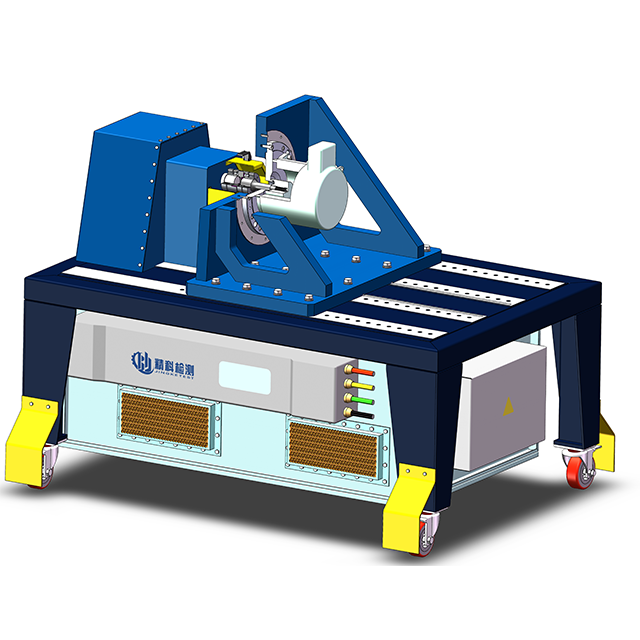
In an External Fixed E-motor EMC Test Bench, the load machine is permanently installed outside the anechoic chamber. It connects to the DUT inside the chamber via a long, shielded drive shaft that penetrates the chamber wall. The dynamometer sits in a separate mechanical room, completely isolated from the RF measurement environment. A specialized RF-sealed bulkhead bearing assembly allows the shaft to spin at high speeds while maintaining the shielding effectiveness of the chamber wall.
This configuration provides maximum isolation of dynamometer electrical noise. Because the massive load machine and its associated power cables remain outside the chamber, they cannot influence the radiated emission measurements. It preserves valuable anechoic chamber volume, allowing smaller, less expensive chambers to test large e-axles. It also simplifies the cooling, maintenance, and acoustic management of the load machine. Technicians can access the dynamometer without disrupting the sensitive test setup inside the chamber.
However, this setup requires complex, permanent facility modifications. Detailed preparation of the anechoic chamber wall is necessary to support the heavy bulkhead bearing. It demands extreme alignment precision. Any misalignment between the external dyno and the internal DUT causes severe vibration. The longer drive shafts required to bridge the distance introduce significant mechanical resonance risks. At high RPMs, long shafts hit critical speed thresholds, causing violent vibrations that can destroy the DUT, shatter the carbon fiber shaft, or damage the chamber wall.
A Free-standing E-motor EMC Test Bench positions the entire test setup, including the load machine, entirely inside the anechoic chamber. The dynamometer used in this configuration is specially shielded and EMC-hardened. It is encased in RF-absorbing materials, utilizes heavily shielded power and encoder cables, and features internal filtering to suppress its own electrical noise. The entire assembly sits on a mobile or semi-permanent bedplate within the testing zone.
This configuration offers high flexibility in positioning. Test engineers can move the bench to optimize the distance between the DUT and the measurement antennas according to specific CISPR standards. It utilizes much shorter drive shafts, drastically increasing the mechanical stiffness of the driveline. This allows for ultra-high RPM testing without hitting critical resonance frequencies. It is highly adaptable for testing varying motor topologies, standalone motor electronics, or complex back-to-back configurations without needing to re-align through a chamber wall.
The primary trade-off is that it consumes significant chamber space. Facilities must invest in larger, more expensive anechoic chambers to accommodate the footprint of the bench while maintaining the required antenna distances. It requires an exceptionally low-emission dynamometer to prevent background noise contamination. If the internal dyno's shielding degrades, it will ruin the test data. It also complicates internal thermal management and cable routing. All cooling lines and high-power drive cables for the load machine must be routed through the chamber floor without creating RF leaks.
Feature | External Fixed E-motor EMC Test Bench | Free-standing E-motor EMC Test Bench |
|---|---|---|
Dynamometer Location | Outside the anechoic chamber | Inside the anechoic chamber |
EMI Isolation | Excellent (physical separation) | Relies heavily on dyno shielding |
Drive Shaft Length | Long (passes through wall) | Short (direct connection) |
Max RPM Capability | Limited by shaft resonance | Ultra-high (20,000+ RPM) |
Chamber Space Required | Minimal | Significant |
Installation Flexibility | Permanent, rigid facility modification | Mobile, adaptable bedplate design |
Evaluating the Shielding Effectiveness (SE) of the test bench enclosures, cables, and connectors is paramount. The test bench must not degrade the baseline ambient noise of the anechoic chamber. SE is typically verified using standards like IEEE 299. High-quality benches utilize double-shielded cables with 360-degree EMC cable glands connecting to milled aluminum junction boxes. Any gap in the shielding, even a fraction of a millimeter, acts as a slot antenna at high frequencies. This leaks noise and causes compliance failures.
Data acquisition systems must capture fast, reliable results without introducing conductive EMI paths. E-motor testing requires continuous monitoring of temperature, vibration, torque, and rotational speed. Standard copper sensor wires pick up radiated emissions from the inverter and conduct them back to the control room, destroying signal integrity. Advanced benches integrate fiber-optic communication lines for all sensor data. Fiber optics are immune to electromagnetic interference. They ensure the high-speed interaction of electrical components is captured perfectly while maintaining absolute galvanic isolation between the chamber and the control room.
Procurement teams must evaluate the bench's capacity to handle next-generation EV architectures. The industry is rapidly shifting from 400V systems to 800V and 1200V+ architectures to enable faster charging and higher efficiency. The test bench's HV power supplies, LISNs, and cabling must be rated for these extreme voltages. Modern fully integrated e-axles are becoming heavier and more compact, while motor speeds are exceeding 25,000 RPM. The mechanical bedplate must support massive static loads, and the driveline must be dynamically balanced to handle extreme rotational velocities without catastrophic failure.
Automation and software integration define the operational efficiency of the laboratory. Manual test execution is prone to human error and cannot reliably replicate complex driving cycles. Automated test sequencing allows engineers to program specific torque, speed, and temperature profiles that run synchronously with the EMI receivers. Real-time data logging captures transient events perfectly. Integration with broader laboratory information management systems (LIMS) ensures that test data, calibration records, and compliance reports are securely stored, easily searchable, and reproducible for auditing purposes.
Improper grounding of the test bench components and motor controllers introduces severe measurement errors. High-frequency switching creates parasitic capacitance between the DUT and the metallic bedplate. If grounding is inadequate, high-frequency common-mode currents find unintended return paths through sensor wires or drive shafts. This creates ground loops, leading to massive spikes in conducted emission readings and guaranteed certification failures. These false readings force engineering teams into endless, unnecessary debugging cycles.
Strict adherence to equipotential bonding is the primary mitigation strategy. Standard round grounding wires suffer from the skin effect at high frequencies, rendering them highly resistive. Test benches must use specialized, wide copper grounding straps to provide a low-impedance path for RF currents. Engineers must verify a single-point grounding architecture, ensuring that the DUT, the LISN, and the bedplate all reference the exact same ground potential. Regularly measuring the impedance of the ground connections with a network analyzer ensures the bonding remains effective over time.
Installing heavy e-axle test benches poses a massive risk to the chamber's RF shielding. Routing thick, inflexible HV cables, cooling lines, and fiber optics through the chamber walls can warp the shielding panels or damage the RF gaskets. External fixed systems require cutting large holes in the chamber wall to accommodate the drive shaft bulkhead, creating a permanent weak point in the Faraday cage. If the installation compromises the shielding, external radio stations, cell towers, and radar systems will contaminate the test data.
Mitigating this risk requires utilizing custom waveguide penetrations and RF-sealed bulkheads designed specifically for the frequency range of the chamber. Honeycomb ventilation panels must be used for air exchange to prevent RF leakage. Post-installation, the facility must undergo rigorous SE verification testing. Independent technicians map the chamber walls with signal generators and receivers to detect any leaks. Only after the chamber passes SE verification can the test bench be commissioned for official compliance testing.
Audit your existing anechoic chamber dimensions, floor load capacity, and available wall penetrations to determine the physical feasibility of internal versus external dynamometer placement.
Define your peak dynamic load, maximum RPM, and overload capacity requirements based on your most aggressive EV driving cycle simulations to size the load machine correctly.
Transition all in-chamber sensor cabling to fiber-optic data acquisition systems to eliminate conductive EMI paths and preserve signal integrity.
Engage specialized EMC test system integrators to perform a site-specific shielding effectiveness verification before finalizing equipment procurement.
A: A standard dynamometer measures mechanical performance and uses unshielded metallic components that emit radio frequency noise. An EMC E-motor test bench is electromagnetically hardened, utilizing shielded cables, RF filtering, and non-conductive drive shafts to operate silently, allowing precise measurement of the motor's own electromagnetic emissions.
A: An external fixed configuration places the noisy load machine outside the anechoic chamber, providing superior electromagnetic isolation and saving valuable chamber space. It is ideal for facilities with smaller chambers, though it limits maximum RPM due to the long drive shaft penetrating the chamber wall.
A: A free-standing bench manages its interference by encasing the internal dynamometer in RF-absorbing materials. It uses heavily shielded power cables, specialized EMC cable glands, and extensive internal filtering on the drive cabinet to suppress switching noise before it reaches the chamber environment.
A: The Line Impedance Stabilization Network (LISN) filters high-frequency noise from the high-voltage power supply, provides a standardized radio-frequency impedance for the device under test, and offers a dedicated coaxial measurement port for receivers to capture conducted emissions accurately.
A: Yes. Advanced EMC test benches support static locked-rotor testing to measure magnetic saturation and low-frequency emissions, as well as back-to-back testing where two motors drive each other to simulate dynamic loads, regenerative braking, and real-world driving cycles.
A: Standard metal drive shafts act as antennas, conducting electrical noise and radiating it into the chamber. EMC test benches use non-conductive materials like carbon fiber to break the galvanic connection, preventing noise transfer and ensuring only the DUT's emissions are measured.
A: The inverter's high-frequency switching signals interact with the motor windings, creating complex impedance and resonance phenomena. Testing them together under load captures the true radiated and conducted emissions generated by these interactions, which cannot be replicated by testing the components individually.


