


Views: 0 Author: Site Editor Publish Time: 2026-11-04 Origin: Site


Installing a new testing facility represents a massive capital expenditure where facility constraints and poor site preparation routinely delay commissioning by weeks or months. Without a rigorous factory installation plan, organizations face severe setbacks. These include compromised shielding effectiveness, grounding loops, and failed Site Acceptance Testing (SAT). Such failures directly impact product time-to-market and disrupt engineering schedules. A structured, step-by-step approach to site readiness and equipment deployment minimizes downtime. It ensures strict regulatory compliance with standards like CISPR, ISO, and MIL-STD. Methodical preparation accelerates the transition from installation to active pre-compliance and full compliance testing. Executing a flawless facility integration prevents expensive mid-construction retrofits and keeps your engineering teams on track.
Site Readiness is Non-Negotiable: Dedicated clean power, isolated grounding, and strict spatial clearances (minimum 15 feet around the Equipment Under Test zone) must be verified prior to equipment arrival.
Early Engagement Prevents Bottlenecks: Defining the product's operating modes and preparing auxiliary equipment early ensures the facility's power and data routing can support real-world testing scenarios.
Specialized Infrastructure Demands: Automotive and high-power setups require distinct structural reinforcements, high-voltage safety interlocks, and thermal management systems.
Phased Validation Mitigates Risk: Shielding effectiveness and baseline ambient noise must be measured iteratively during chamber assembly, not just at the end of the project.
Vendor Alignment: Securing comprehensive installation support from a single source ensures seamless integration between the anechoic chamber, instrumentation racks, and test automation software.
The foundation of a successful installation relies entirely on the facility infrastructure meeting exact vendor specifications. Failing to prepare the physical site leads to severe schedule overruns and forces engineering teams into reactive problem-solving. You must validate structural, electrical, and spatial requirements long before the first delivery truck arrives. A high-performance EMC Test System demands an environment completely free from ambient interference and mechanical instability. Concrete slab curing times, moisture barriers, and floor flatness tolerances dictate the success of the chamber assembly. If the floor deviates more than a few millimeters over a three-meter span, the modular shielding panels will not align properly, creating massive RF leaks.
Engage the equipment vendor early in the facility design phase. This collaboration helps teams map out all applicable electromagnetic compatibility test requirements before pouring concrete or running conduit. You must define the Equipment Under Test (EUT) operating modes upfront. Knowing exactly how the product operates under maximum load ensures the facility design accommodates the necessary power draw, thermal output, and data acquisition lines. Prepare and map the footprint for all auxiliary support equipment required to drive the EUT during active testing.
If your product requires hydraulic pumps, external chillers, or heavy-duty power supplies, position these outside the shielded environment. They must remain close enough to route cables through penetration panels without signal degradation. Long cable runs introduce voltage drop and increase the risk of picking up ambient noise. Plan the exact routing paths for these auxiliary lines early. Specify the exact connector types and pinouts required for the penetration panels to avoid drilling custom holes through the shield later.
Define the footprint requirements for the anechoic chamber, control room, and amplifier rooms. You must detail the necessity of a 15-foot clear space around the primary staging area and EUT zone. This clearance allows for safe material handling, modular panel assembly, and reliable grounding access. Forklifts and scissor lifts need room to maneuver heavy structural steel and delicate shielding panels. Moving a 1,000-pound RF door into position requires significant swing space and heavy lifting equipment.
Assess the floor load-bearing capacity meticulously. Fully lined chambers utilize thousands of ferrite tiles and heavy hybrid absorbers. The concrete slab must support this massive concentrated weight without cracking or settling over time. A settling foundation pulls the RF shield seams apart. Verify the structural integrity of the host building's ceiling as well. Many large chambers require seismic bracing tied directly into the facility's roof trusses to meet local building codes.
Outline the requirements for isolated, low-impedance grounding systems to prevent ground loops. A single-point ground configuration is mandatory for accurate, repeatable measurements. Drive dedicated grounding rods deep into the soil and measure the earth conductivity. The target impedance usually falls below one ohm. Specify clean power routing from the main facility breaker. Utilize heavy-duty line filters to isolate the test environment from facility electrical noise generated by elevators, heavy machinery, or fluorescent lighting.
Detail the HVAC integration carefully. Climate control systems must not introduce electromagnetic interference or compromise RF shielding integrity. All ductwork must interface with the chamber via specialized honeycomb waveguide vents. These vents allow conditioned air to flow freely while blocking external radio frequencies from entering the test zone. Ensure the HVAC contractor understands that they cannot screw standard sheet metal ducts directly into the chamber walls. They must use dielectric breaks to prevent the ductwork from becoming an unintended grounding path.
Organizations must decide between managing facility upgrades internally or relying on a single-source vendor for end-to-end deployment. Each approach carries distinct logistical challenges and resource requirements. Selecting the right deployment strategy depends on internal engineering bandwidth, facility management capabilities, and strict project deadlines. A mismanaged phased deployment often results in contractors pointing fingers when the final shielding effectiveness test fails.
Evaluate the return on investment of turnkey systems where a single-source provider manages the entire lifecycle. Comprehensive EMC Test System Installation Support covers system design, chamber construction, instrumentation integration, and software calibration. This unified approach drastically reduces integration risk. When hardware, software, and operator training are delivered by a single engineering team, accountability remains centralized.
You avoid the common trap of multiple vendors blaming each other for software handshakes or cable routing mismatches. Turnkey solutions typically reach operational status much faster because the installation crew intimately understands the specific equipment tolerances. They know exactly how much torque to apply to the panel bolts and exactly how to route the fiber optic lines without exceeding the minimum bend radius. This expertise prevents the rework that plagues internally managed projects.
Outline the responsibilities of internal facility managers if you choose a phased or internally managed deployment. Internal teams handle pouring concrete, running primary utilities, and installing structural supports. Trade-offs exist between the perceived savings of internal labor versus the risk of timeline delays. Misaligned technical specifications often occur when internal contractors misinterpret specialized RF requirements.
A standard electrician might loop ground wires in a way that creates a massive antenna for ambient noise. A plumber might run copper piping straight through a penetration panel without installing the required waveguide pipe, instantly ruining the chamber's shielding effectiveness. If internal teams handle the facility upgrades, strict oversight by an RF engineer is required to ensure every conduit, breaker, and HVAC duct meets stringent shielding criteria.
Deployment Strategy | Primary Advantages | Inherent Risks | Best Suited For |
|---|---|---|---|
Turnkey Vendor Installation | Single point of accountability, faster commissioning, guaranteed SAT compliance. | Requires higher initial capital outlay for comprehensive labor and project management. | Organizations needing rapid deployment with limited internal RF engineering resources. |
Internally Managed Phased Deployment | Utilizes existing facility maintenance teams, potential reduction in upfront labor costs. | High risk of RF leaks, ground loops, and schedule delays due to misaligned specs. | Companies with highly experienced in-house RF facility engineers and flexible timelines. |
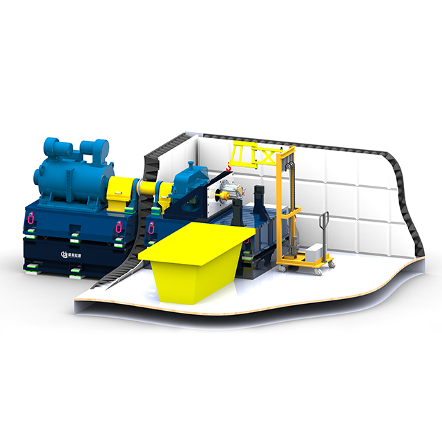
Automotive testing requires handling dynamic loads, high voltages, and complex mechanical integration that standard commercial setups do not face. An Automotive EMC Test System must safely manage the extreme power demands of modern electric vehicle (EV) powertrains. This requires robust structural planning, advanced thermal management, and fail-safe safety interlocks to protect both the operators and the sensitive instrumentation. The physical forces generated by spinning a high-torque motor inside a shielded box demand heavy-duty engineering.
Detail the structural requirements for routing heavy drive shafts through the chamber wall. An External Fixed E-motor EMC Test Bench places the noisy dynamometer outside the shielded environment. This setup requires specialized RF-shielded feedthroughs to maintain enclosure integrity while the shaft spins at high RPMs. The feedthrough acts as a waveguide operating below cutoff, allowing the mechanical shaft to pass through while blocking electromagnetic waves.
You must implement strict vibration isolation techniques. Mechanical resonance transferred from the external dynamometer to the chamber wall degrades RF shielding seams over time. Heavy-duty vibration dampeners and flexible coupling mechanisms absorb these kinetic forces before they reach the modular panels. The concrete foundation for the external dynamometer must be physically decoupled from the chamber's foundation slab to prevent low-frequency vibrations from shaking the sensitive measurement antennas.
Outline the precision alignment process for in-chamber dynamometers. A Free-Standing E-motor EMC Test Bench operates entirely within the shielded room. This requires specialized low-emission components to ensure the bench itself does not fail the ambient noise baseline. The dynamometer's internal inverters and control electronics must be heavily shielded and filtered.
Specify floor anchoring requirements meticulously. The concrete slab must feature embedded steel mounting plates to secure the high-torque motor. Use non-reflective, low-permittivity materials for all support structures near the EUT. This minimizes electromagnetic field distortion during radiated emissions testing. The antennas must measure the motor's true emissions rather than reflections bouncing off a massive steel test stand. Fiberglass or specialized treated wood structures often replace standard steel framing near the test zone.
Define the safety protocols for routing high-voltage DC power into the chamber. Modern EV testing routinely involves 800V to 1000V+ architectures. These power lines must pass through heavy-duty EMI filters that handle massive current without saturating the internal magnetic cores. Saturated filters lose their attenuation properties, allowing inverter switching noise to flood the facility's power grid.
Evaluate the integration of liquid cooling lines. High-power inverters and motors generate immense heat under load. Non-conductive coolant lines must penetrate the chamber via specialized waveguide pipes. Integrate safety interlocks and emergency shutdown systems directly with the main test software. If the chamber door opens or a thermal runaway event occurs, the system must instantly sever high-voltage power and dump residual capacitance safely. Install dedicated exhaust systems to handle potential battery off-gassing events during destructive testing.
A chronological breakdown of the physical installation highlights critical path dependencies. Managing this sequence properly prevents rework and ensures the facility meets all performance guarantees. Each phase requires specific engineering sign-offs before the next stage can begin. Skipping a verification step guarantees failure during the final commissioning phase.
Establish a process for receiving, uncrating, and inspecting sensitive RF instrumentation. Chamber panels, heavy doors, and delicate antennas must be checked for transit damage immediately upon arrival. A dented panel edge or a bent antenna element ruins measurement accuracy. Establish a clean staging area to prevent contamination of RF contact surfaces.
Dust, oil, or debris on the modular panel edges degrades the electrical conductivity of the seams, leading to RF leaks. Installers must wear gloves when handling the beryllium copper finger stock. Inventory every cable, connector, and ferrite tile. Missing a single customized penetration panel halts the entire assembly process for weeks while a replacement is fabricated. Organize the hardware bins meticulously; mixing up the zinc-plated bolts with standard steel bolts causes galvanic corrosion over time.
Follow a strict sequence for erecting the modular RF shield. Install the floor panels first, followed by the walls, and finally the ceiling structure. Mount the heavy RF doors and ensure the pneumatic or mechanical latches compress the finger stock evenly. Conducting intermediate shielding effectiveness (SE) tests before absorber installation mitigates massive implementation risks.
You must catch and remediate RF leaks early. Testing the bare metal shell allows engineers to locate leaky seams with a sniffer probe and tighten the bolts. Once thousands of ferrite tiles and foam absorbers are glued or screwed to the walls, accessing those seams becomes nearly impossible. The intermediate SE test uses a transmitting antenna inside the bare chamber and a receiving antenna outside, sweeping across the frequency band to verify the raw metal enclosure meets the specified attenuation levels (e.g., 100 dB at 1 GHz).
Implement best practices for routing RF cables, fiber optics, and power lines through the penetration panels. Keep high-voltage power lines strictly separated from sensitive coaxial measurement cables to prevent crosstalk. Run power lines in grounded metal conduit and use shielded twisted pair for low-frequency data lines.
Ensure proper bend radii for all high-frequency connections. Kinking a rigid coaxial cable alters its impedance and ruins measurement accuracy. Apply exact torque specifications to all RF connectors using calibrated torque wrenches. Over-tightening damages the dielectric, while under-tightening creates intermittent signal loss and high voltage standing wave ratios (VSWR). Label every cable at both ends with durable, heat-shrink markers. Tracing an unlabeled fiber optic line through a raised floor during a troubleshooting session wastes hours of engineering time.
Power up the amplifiers, receivers, and antennas. Arrange the equipment precisely as required for initial storage and baseline testing. Adjust the chamber conditions to meet specific military or commercial environmental standards, such as MIL-STD-461 or MIL-STD-810D. Verify the turntable and antenna mast communicate seamlessly with the control software.
Run baseline ambient noise sweeps across the entire frequency spectrum. This verifies the chamber meets the required noise floor specifications, such as CISPR 25 for automotive testing. The ambient noise must measure significantly below the lowest emission limit of your intended test standards. If the baseline fails, engineers must hunt down the internal or external noise source before proceeding. Common culprits include LED lighting drivers inside the chamber or unshielded Ethernet cables plugged into the control room PCs.
Addressing the most frequent technical hurdles encountered during the final commissioning phase keeps the project on track. Even with perfect planning, unexpected physical anomalies arise when integrating complex RF environments with standard building utilities. Knowing how to troubleshoot these anomalies separates successful deployments from endless engineering nightmares.
Troubleshooting unexpected RF leakage requires patience and specialized gear. Leakage often originates from facility lighting, poorly installed HVAC penetrations, or misaligned RF doors. Utilize sniffer probes, signal generators, and spectrum analyzers to pinpoint compromised joints. Modulate the test signal with a 1 kHz tone to easily identify the leak audibly through the receiver.
If a door frame warps slightly under the weight of the steel, the finger stock will not seat properly. Mitigation involves adjusting the door hinges, replacing damaged beryllium copper gaskets, or applying conductive tape temporarily to isolate the leak source before executing a permanent mechanical fix. Check the waveguide vents; sometimes contractors accidentally paint over the honeycomb cells, bridging the electrical connection and allowing RF to pass through.
Identify common-mode currents and ground loops between the instrumentation rack and the chamber ground. Ground loops occur when multiple conductive paths to earth exist, creating a large loop antenna that picks up 50/60Hz mains hum and broad-spectrum noise. A laptop plugged into a wall outlet and connected via USB to a receiver inside the rack instantly creates a ground loop.
Mitigation requires implementing strict single-point grounding rules. All equipment must tie back to one central ground bus bar using heavy-gauge braided copper straps. Utilize isolation transformers and fiber optic data links where necessary to break conductive paths between the control room PCs and the sensitive receivers inside the shielded environment. Clamp-on current probes help identify which cables are carrying unintended common-mode currents.
Define the criteria for a successful SAT clearly in the initial contract. This testing includes normalized site attenuation (NSA) and field uniformity (FU) measurements to prove the chamber performs linearly across all required frequencies. The NSA test verifies that the chamber mimics an ideal open area test site (OATS), while the FU test ensures the RF field generated during immunity testing is even across the entire EUT area.
Establish a clear handover protocol. Ensure all auxiliary equipment is tested under load. Comprehensive operator training must be completed so internal teams can immediately begin pre-compliance testing. A rushed handoff leaves internal engineers guessing how to configure the automation software, leading to false test failures and frustration. The vendor must provide detailed calibration certificates for every antenna, cable, and receiver in the system.
Audit your facility's power and grounding infrastructure to confirm it meets isolated, low-impedance requirements.
Map out the exact 15-foot clearance zones for staging and material handling before scheduling equipment delivery.
Schedule an intermediate shielding effectiveness test immediately after the bare metal shell is erected.
Assign a dedicated internal project manager to coordinate daily with the vendor's installation engineering team.
Verify all auxiliary support equipment footprint dimensions and power draws to finalize penetration panel layouts.
A: A minimum of 15 feet of clear space is required around the staging area, chamber footprint, and Equipment Under Test (EUT) zone. This allows for the safe handling of heavy modular panels, maneuvering of scissor lifts, and reliable access for grounding and structural bolting.
A: An external fixed bench places the dynamometer outside the chamber, routing the drive shaft through a specialized RF feedthrough. A free-standing bench places the entire motor and load unit inside the chamber, which requires highly specialized, low-emission components to prevent ambient noise failure.
A: Testing the bare shielded enclosure before installing absorbers allows engineers to locate and fix RF leaks at the seams. Once heavy ferrite tiles and foam absorbers are mounted over the walls, accessing and repairing those leaky seams becomes nearly impossible without major teardowns.
A: A fully integrated system allows engineering teams to conduct rigorous pre-compliance testing in-house. This identifies EMI issues early in the design cycle, helping manufacturers avoid extensive board redesigns, schedule delays, and repeated trips to third-party compliance laboratories.
A: Automotive systems require a dedicated, low-impedance earth ground, measuring less than one ohm. This must be configured as a strict single-point ground to prevent ground loops, eliminate common-mode currents, and ensure highly accurate, repeatable emission measurements.
A: HVAC systems must interface with the chamber using specialized honeycomb waveguide vents. These vents allow airflow while acting as a waveguide below cutoff, blocking electromagnetic frequencies from entering or exiting the test environment. Dielectric breaks must also be installed on the ductwork.


